UCLA Rocket Project
Horizontal Propulsion Test Stand
Isolating 5,635 lbf-s through 3 Mojave static fires
Overview
| Stand Weight | 33.7 lbm |
| Engine Weight | 25.9 lbm |
| Engine Thrust | 640 lbf |
| Factor of Safety | > 2.0 |
| C-Strut Ult. Str. | 45 ksi |
| Bolt Ult. Str. | 120 ksi |
| Design | SolidWorks · Whiteboard · Napkin |
| Analysis | Microsoft Excel · Ansys Mechanical |
Concept to prototype
Impulse isolated
Reaction moment
Problem
The heritage test stand required readjustment because its legs were constrained at a single joint, leaving them free to rotate laterally. Critically, the stand had to interface with fixed bolt holes at the test site. Thrust measurement was not isolated from the stand structure, mixing off-axis bearing loads. The heritage design reportedly took weeks of machining time, and our year’s hybrid test campaign could not begin until we had a test stand.
Approach
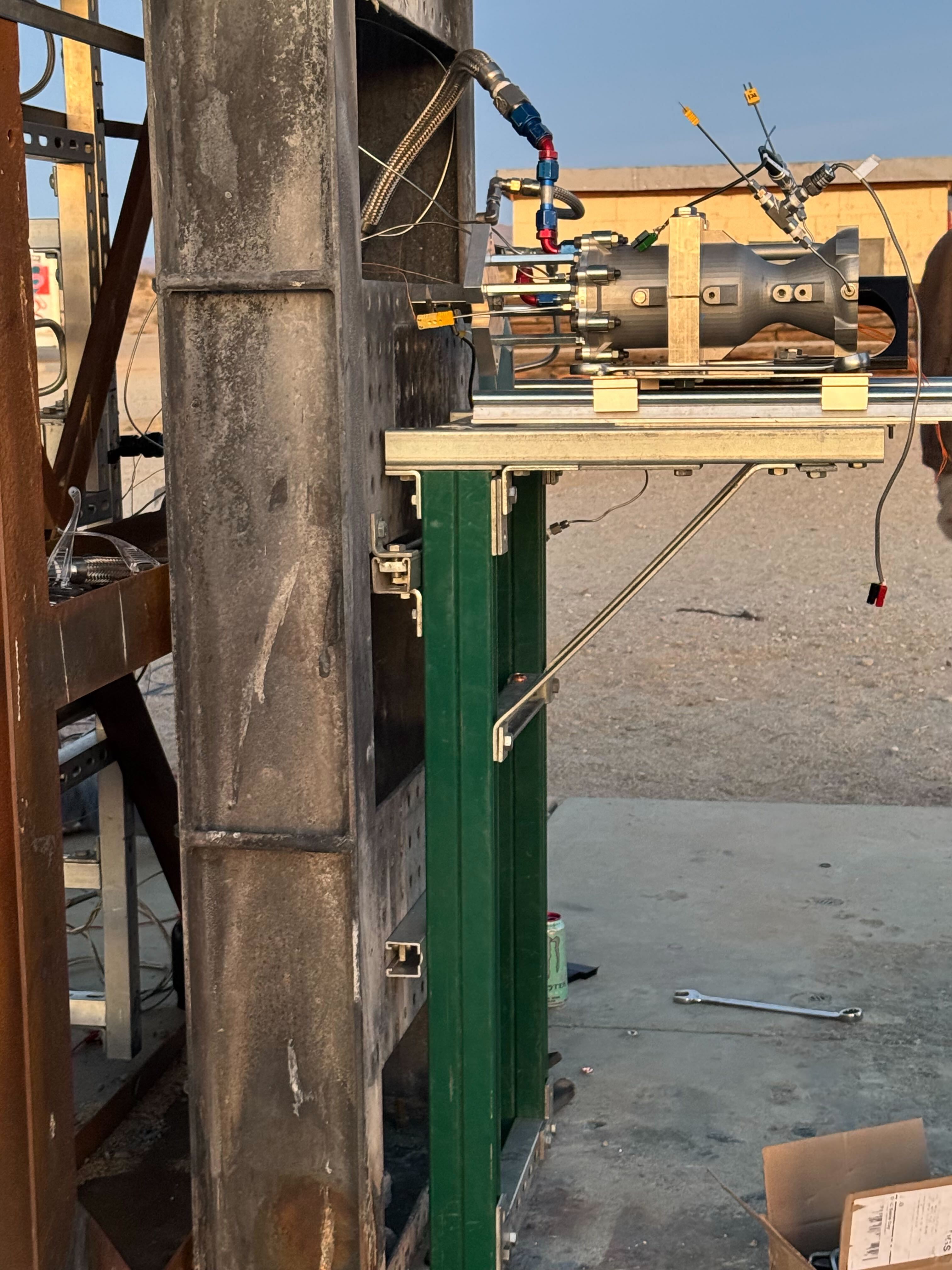
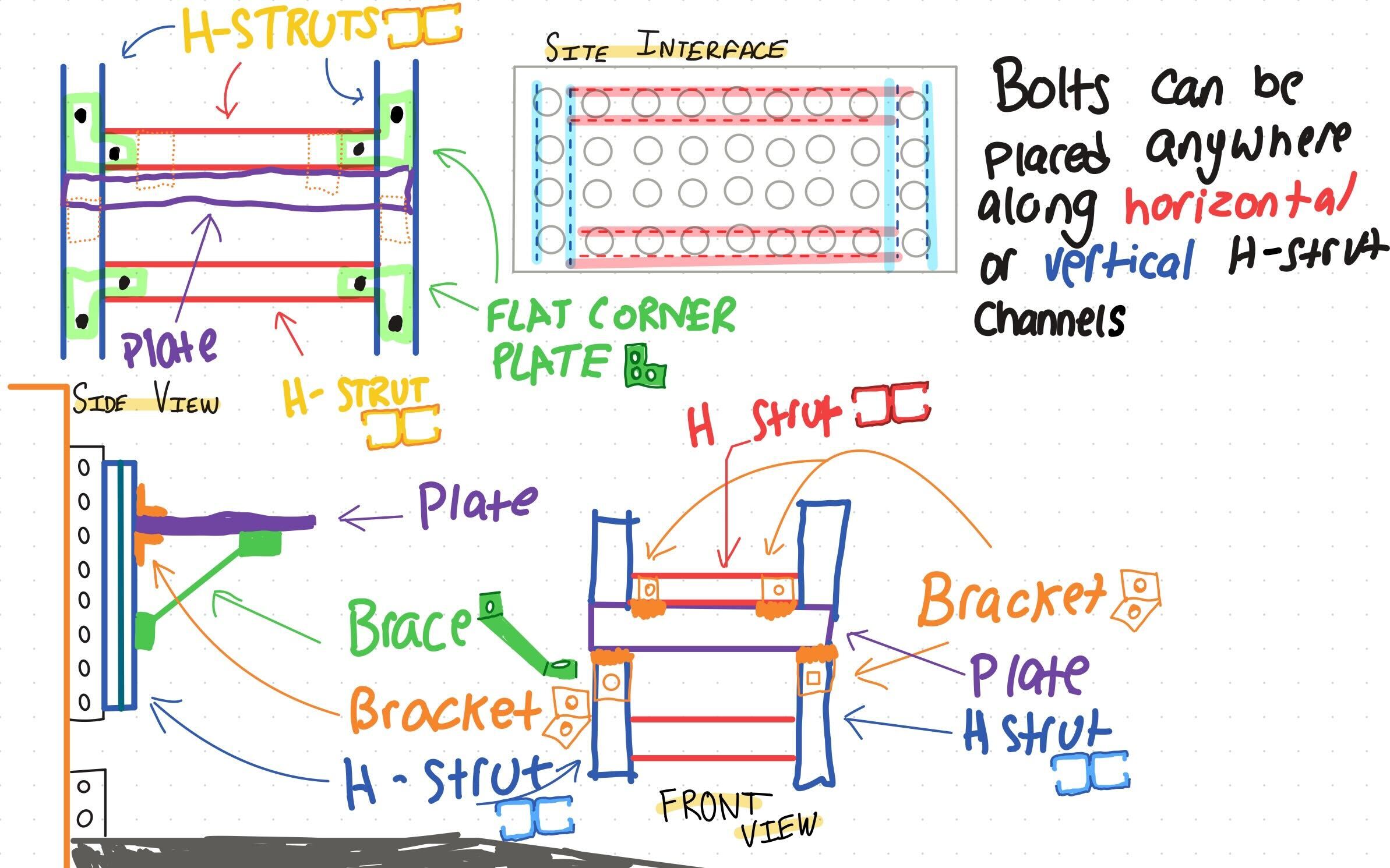
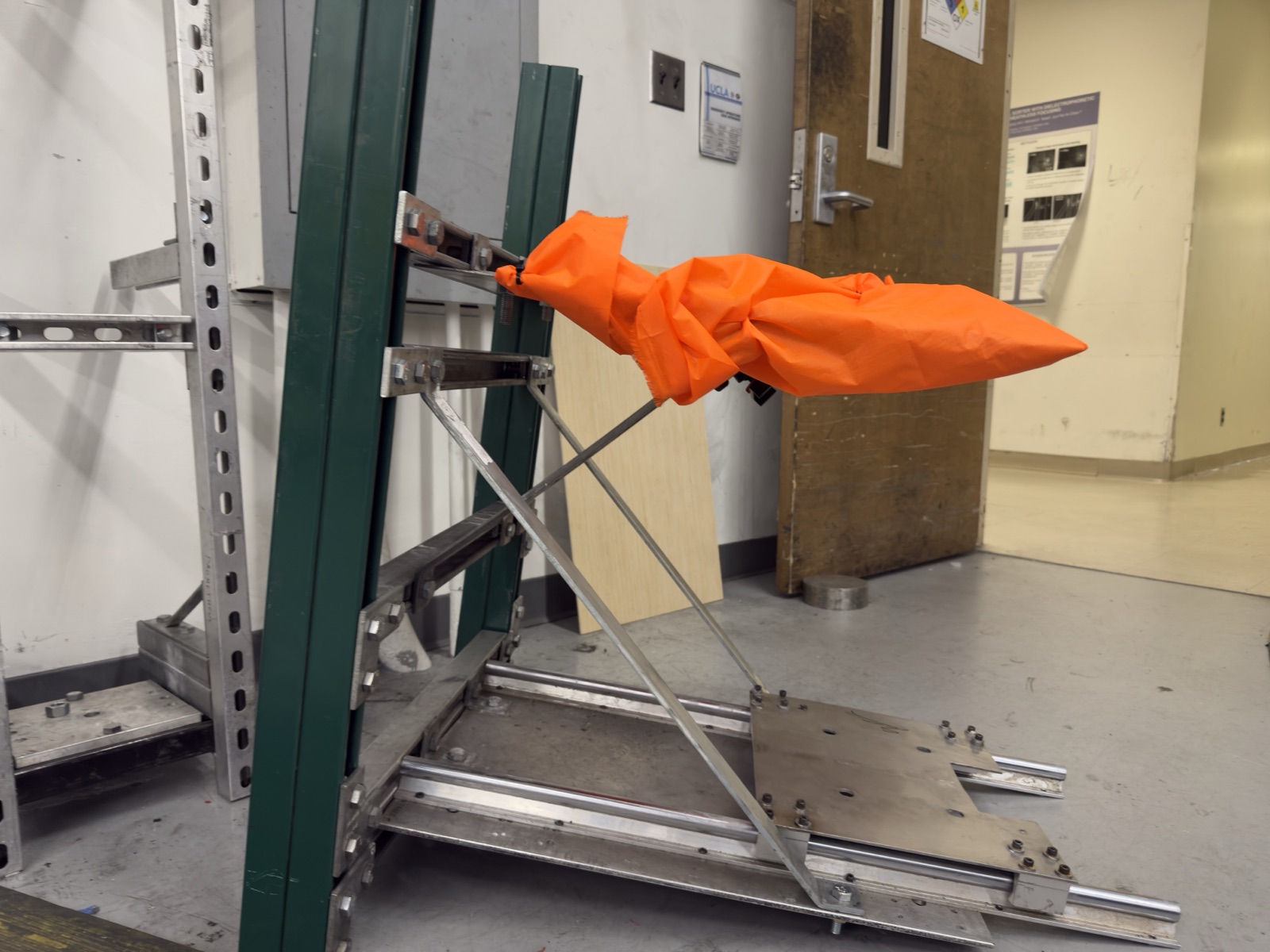
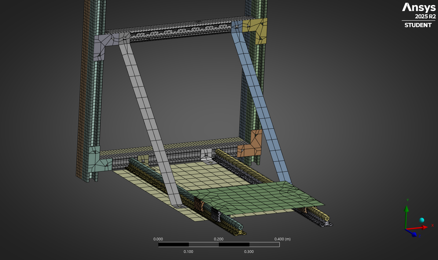
Rather than improving the problematic leg struts, I deleted the legs entirely and redesigned the stand to mount directly to the site’s plates. Rebuilding from the site constraints and the governing propulsion calc. sheet, I reframed the primary structure as two horizontal H-struts forming a square frame that interfaces directly with the site’s plates, with two vertical H-struts as uprights. This made the stand highly adjustable both vertically and horizontally. Cantilever loads on the base plate were addressed by adding diagonal braces, converting the shelf into a truss configuration.
Build
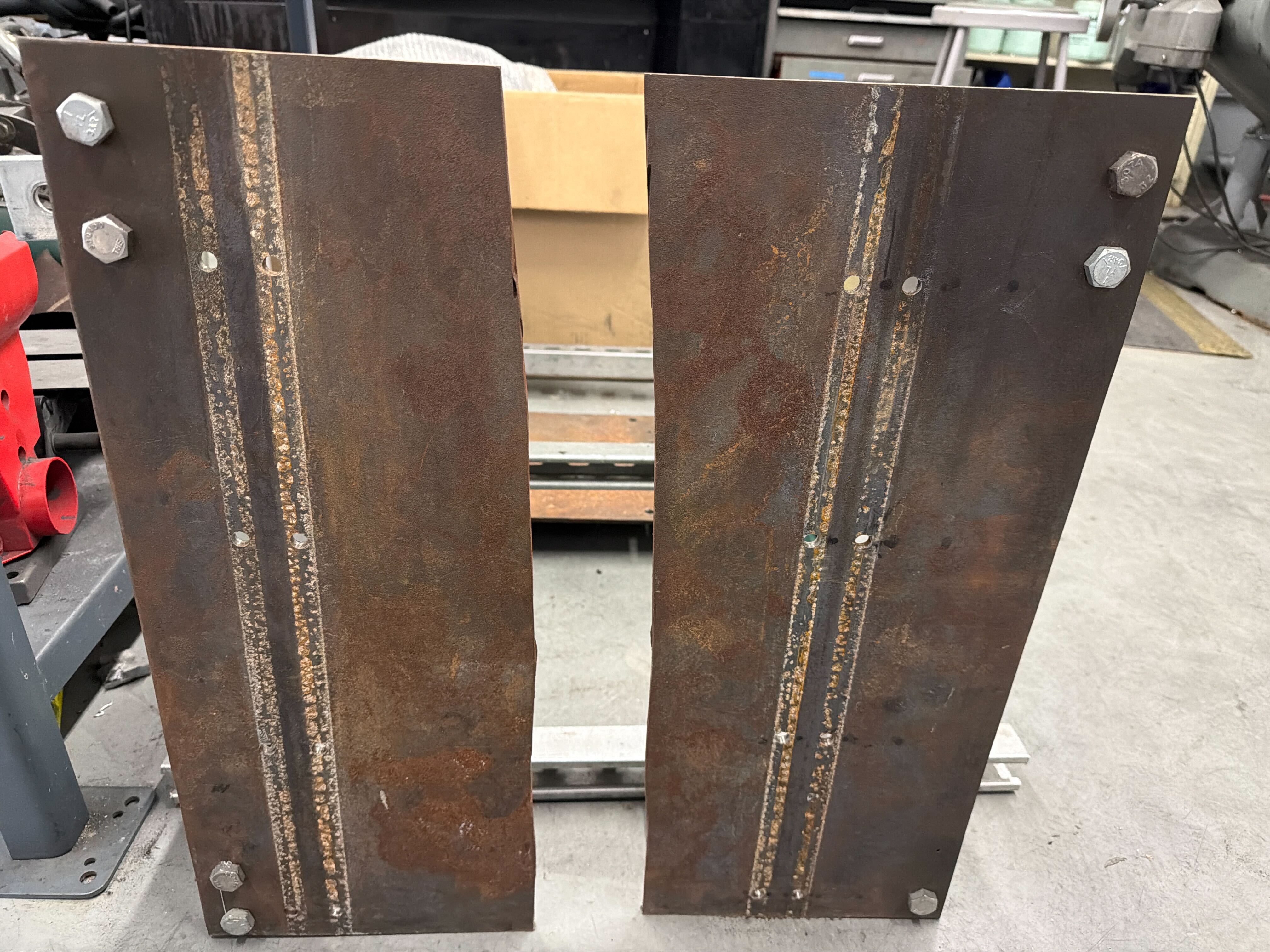
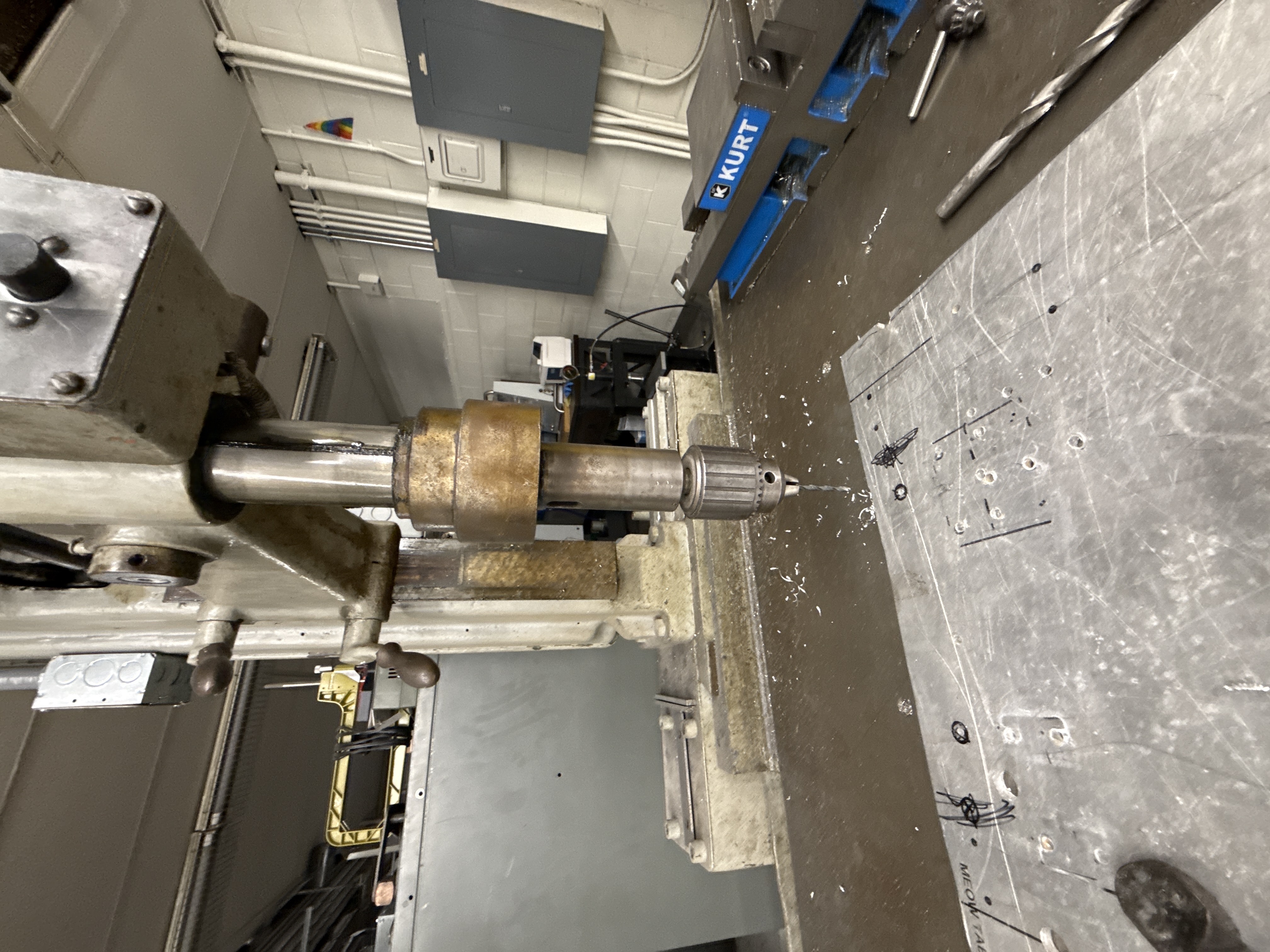
The stand went from slack thread to completed build in three weeks. During assembly, I saw that the vertical struts had clearance above the base plate for a blast shield to be added directly to the stand rather than the prior configuration, which placed the shield under the oxidizer tank mount, further from any potential blast origin. I machined the aluminum base plate with the 3-axis mill, drilling hole patterns for the linear rails, mounting brackets, and brace attachment; the steel blast shield required a central hole for the oxidizer flex hose and bolt patterns for the braces.
Analysis
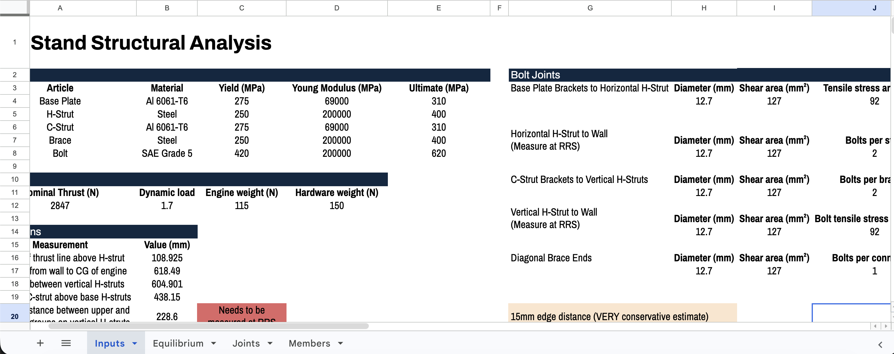
I performed structural analysis on every bolted joint using loads from our propulsion calculation sheet, applying a 1.7× dynamic load factor for a factored thrust of 1,088 lbf. Joints analyzed included the base plate brackets to horizontal H-strut at full factored thrust and the horizontal H-strut to wall plates at 544 lbf, with failure modes checked across bolt shear, bearing, tear-out, brace buckling, and brace tension. All joints exceeded the 2.0 minimum factor of safety.
Result
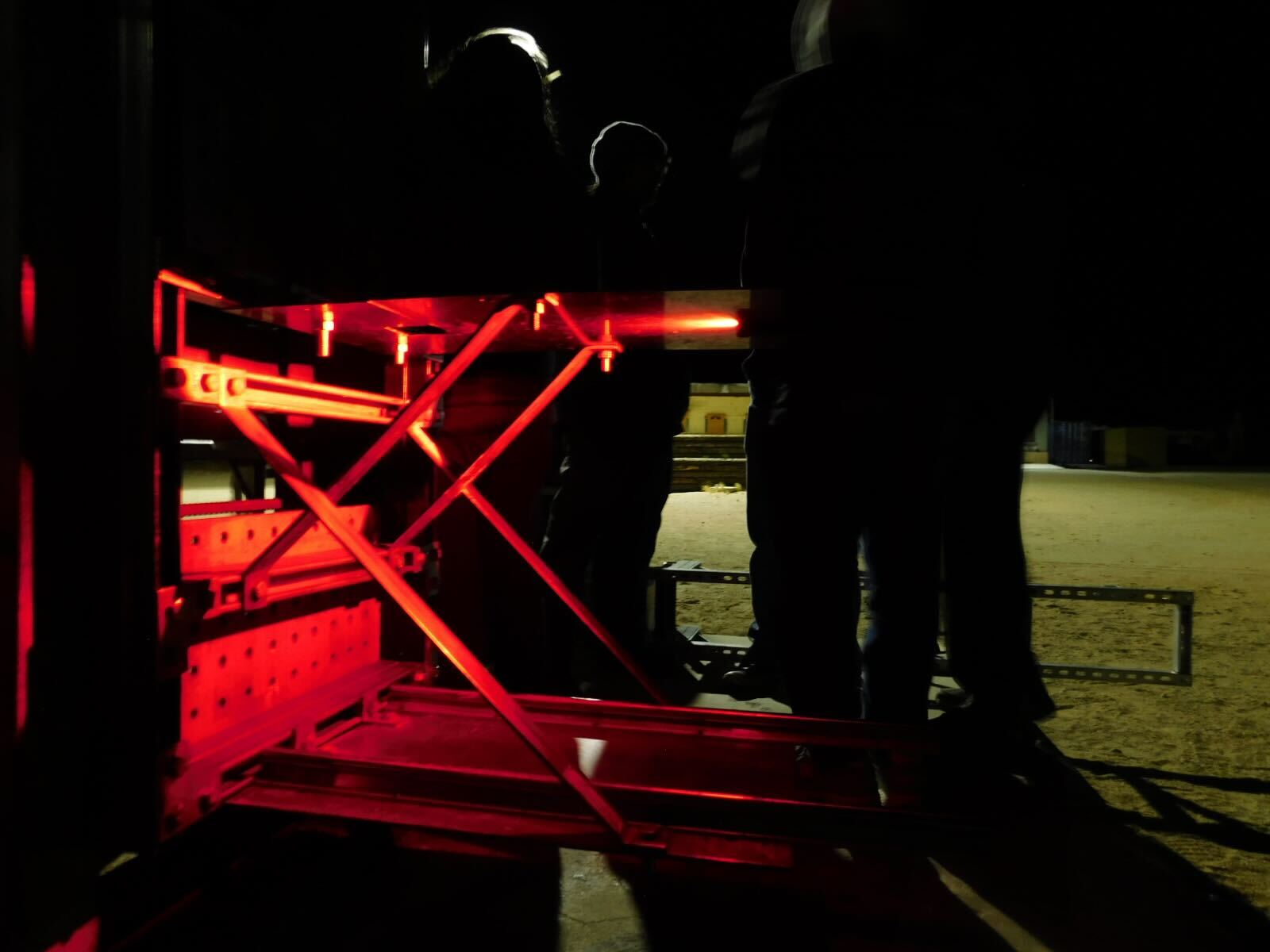
The stand was integrated on the first attempt at the site with zero adjustments required, cutting integration time by one hour. It supported a full test campaign: several high-pressure leak-rate tests, two CO₂ cold-flows, and three N₂O/HTPB static fires across three different SRAD engine designs. The blast shield, relocated to the stand during build, absorbed direct blast exposure at the final hotfire, which validated the decision to position it closer to the potential failure origin.
Reflection
Speed is a tactical advantage. Ownership through design, analysis, build, and site integration reduced a full development process into twp weeks and surfaced issues with a fast feedback loop. Three weeks from the first message to a stand that took a full-pressure blast is a pace worth repeating, and it was possible only because the structure was simple enough to build quickly. Simplicity was critical to early designs. The highest-leverage decision was removing the legs entirely rather than improving them; why optimize a flawed feature?